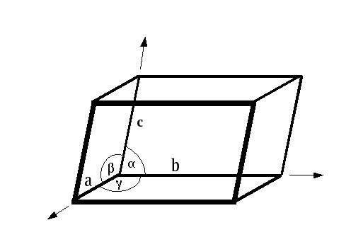
X-ray data collection often seems more theoretically challenging that it actually is - but there are several important choices to make and some knowledge of crystal symmetry is helpful. Theory is important to the extent that it is good to understand the basis of what you are collecting, but the finer nuances of diffraction space are less important than making sure you've got the parameters right in Denzo.

The unit cell is usually not the smallest unique volume in the crystal - that would be the asymmetric unit. Unit cells contain from one to many asymmetric units, arranged in patterns characteristic of what symmetry is in the crystal (i.e. the space group). Each asymmetric unit contains the same environment as any other asymmetric unit i.e. they are all equivalent to each other. One asymmetric unit can be mapped to any other one by a combination of symmetry operations, and therefore an entire unit cell (and hence crystal) can be built up from the contents from a single asymmetric unit and the symmetry operators.
There is an inverse relationship between the dimensions in real space and the dimensions in reciprocal space (i.e. diffraction space). The real space unit cell dimensions a,b,c,α,β,γ have corresponding reciprocal space counterparts called a*,b*,c*,α*,β*,γ*. The relationships are:
         a* is parallel to b X c (i.e. perpendicular to the b/c plane)
         b* is parallel to c X a (perpendicular to the a/c plane)
         c* is parallel to a X b (perpendicular to the a/b plane)
         a is parallel to b* X c*
         b is parallel to c* X a*
         c is parallel to a* X b*
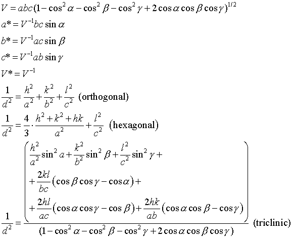
Symmetry in a crystal is constrained by the fact that one must be pack the identical asymmetric units into a unit cell, such that the environment of each asymmetric unit is identical. These constraints reduce the number of possible types of symmetry to relatively few:
Mirror planes and inversion center symmetries inevitably invert the chirality of chiral centers (e.g. flipping L-amino acids to D-amino acids), so are not compatible with compounds that aren't a racemic mixture of chiral molecules. Proteins and nucleic acids are non-racemic mixtures of very chiral molecules, so the only symmetries that can occur in macromolecular crystals are pure rotations, screw axes and pure translations. This simplifies things a lot.
Symmetry within the unit cell also imposes some limitations on what values the unit cell dimensions may occupy. The so-called seven crystal systems can be sorted according to what symmetries they must minimally contain:
| Crystal System | Rotational symmetry | Cell dimension constraints |
|---|---|---|
| Triclinic | 1-fold | none |
| Monoclinic | 2-fold | α=γ=90 degrees |
| Orthorhombic | three perpendicular 2-folds | α=β=γ=90 degrees |
| Tetragonal | 4-fold | a=b, α=β=γ=90 degrees |
| Trigonal | 3-fold | a=b, α=β=γ=120 degrees |
| Hexagonal | 6-fold | a=b, α=β=γ=120 degrees |
| Cubic | 3 and 2-folds | a=b=c, α=β=γ=90 degrees |
although in some cases the crystals will contain more than the minimum symmetry. In turn the systems can contain one or more Bravais Lattices:
| Crystal System | Lattice |
|---|---|
| Triclinic | P |
| Monoclinic | P, C |
| Orthorhombic | P, I, F |
| Tetragonal | P, I |
| Trigonal | P, R |
| Hexagonal | P |
| Cubic | P, F, I |
These 14 Bravais Lattices provide no additional rotational symmetry, but may give additional translational symmetry to the unit cell. P is Primitive (no additional symmetry), C is C-face centered: for each atom at (x,y,z) there is another one at (x+1/2, y+1/2, z) where the "1/2" means "half of the unit cell edge along that direction". I is body-centered, so that for each atom at (x,y,z) there is another one at (x+1/2, y+1/2, z+1/2) and F is all-face centered, namely for (x,y,z) there are also atoms at (x+1/2, y+1/2, z), (x+1/2, y, z+1/2) and (x, y+1/2, z+1/2).
Symmetry operators like the ones above are expressed in fractional coordinates where each unit cell location is expressed as a linear sum of fractional unit cell translations:
(where a,b,c are the unit cell vectors and x,y,z are the fractional scalars denoting a location within the unit cell). For orthorhombic, tetragonal and cubic space groups the fractional locations (x,y,z) are the same as the more familiar cartesian locations (X,Y,Z) divided by the unit cell edges i.e.:
Fractional coordinates are periodic so you can add and subtract integers from them and it refers to the identical location (but in adjacent unit cells). You can always map them to the range 0...1 by this addition or subtraction.
If your asymmetric unit contains more than one molecule, then you will also have non-crystallographic symmetry which has some of the same constraints as crystallographic symmetry (no mirror or inversion symmetries) but can otherwise be in an arbitrary position, direction and rotation. Except in very special cases (e.g. high-symmetry viral capsids), non-crystallographic symmetry is not considered for the purposes of data collection but it can be very useful during map interpretation (averaging) and refinement (ncs restraints). The downside is that it tends to make your unit cell bigger than it might otherwise be. As of writing my "personal best" is 56 distinct momoners in the asymmetric unit with the larger crystal form of the 20S proteasome.
Symmetry in real space is a combination of rotations and translations that give rise to a unique pattern of symmetry elements called the space group. Each space group is a member of a Bravais Lattice, and a Crystal Class. However in diffraction space, the translational components of symmetries are not relevant to the symmetry of the diffraction pattern. Only the rotational parts of the operator cause symmetry in diffraction space. As an example the symmetry operator (-x,y,-z) as found in the space group P2 has the same effect in diffraction space as the symmetry operator (-x,y+1/2,-z) as found in the space group P21. It generates symmetry between reflections (h,k,l) and (-h,k,-l) in both cases. This means that several different space groups can have the same diffraction symmetry, because the relative location of symmetries is not relevant (only their direction and type). P2 and P21 have exactly the same diffraction pattery symmetries for this reason. Different space groups that have the same angular relationships of symmetry elements are said to have the same point group.
For example, the space groups in the monoclinic crystal system must have a single 2-fold rotation or screw axis along the b-axis of the unit cell (by convention). There are three of these space groups for proteins and nucleic acids: P2, P21, C2. Both P2, P21 are Primitive lattices and so can be called Primitive Monoclinic, but C2 is C-face centered Monoclinic. Since these are different space groups the precise arrangement of the symmetry elements is different between each space group, i.e. the symmetry operators in different locations in real space. However they all have a 2-fold axis parallel to the unit cell b-axis. When translation components of the symmetries are removed, they all have the same symmetry in diffraction space, i.e. that of point group 2, or actually 2/m if you take into account Friedel's Law. For P2, P21 and C2 the intensity of reflection (h,k,l) is identical to that of reflection (-h,k,-l). If one includes Friedel's Law (h,k,l) is also related to (-h,-k,-l) - note the inversion symmetry here - and (h,-k,l). Freidel's Law applies for native datasets but the extra symmetry is broken in the presence of significant anomalous scattering.
| Crystal System | Point Group | Laue Class |
|---|---|---|
| Triclinic | 1 | -1 |
| Monoclinic | 2 | 2/m |
| Orthorhombic | 222 | mmm |
| Tetragonal | 4 | 4/m |
| 422 | 4/mmm | |
| Trigonal | 3 | -3 |
| 32 (312 and 321) | -3m | |
| Hexagonal | 6 | 6/m |
| 622 | 6/mmm | |
| Cubic | 23 | m-3 |
| 432 | m-3m |
Note that because crystal classes specify only certain minimal symmetries, there is often more than one point group per crystal system. For simplicity I only show the protein-relevant point groups here (there are others).
It can be shown that in the absence of anomalous scattering, that the intensity of the reflection with Miller indices (h,k,l) is the same as that of the reflection (-h,-k,-l). This is called Friedel's Law. The consequence of Friedel's Law is that even if the space group lacks a center of symmetry, the diffraction pattern is centrosymmetric. In this case, point group 2 becomes point group 2/m by the action of Friedel's Law, and point group 222 becomes point group mmm, etc. mmm is called the Laue Class of the point group 222. While I don't suggest memorizing Laue classes, you should be aware of their existence and the extra symmetry that gives rise to them. For SAD, SIRAS or MAD data collection, which relies on anomalous scattering, Friedel's Law is invalid. Friedel's Law does not apply where anomalous scattering is significant. We generally ignore the very small amount of anomalous scattering that occurs from light elements (C, N, O, S, P) at typical wavelengths used in data collection. It's there, but it's way down in the noise level.
During data collection, the various symmetry-related reflections are observed independently. During data integration (DENZO), these reflections are also processed independently. However during data scaling (SCALEPACK) these individual observations of symmetry related copies of the "same" reflection are merged together to produce the unique data. Unique data no longer has any symmetry redundancy within it - i.e. no reflection is related to any other one within the unique set by crystallographic symmetry. Comparison of symmetry-related reflections that should be identical is the basis for most of the data processing statistics, e.g. Rsymm . There's some ambiguity over the usage of Rsymm and Rmerge - I used the former (symm) to refer to internal agreement with symmetry, and I use the latter to refer to the merging R-factor when I merge multiple datasets together. Not everyone follows this rule. The PDB asks for both Rmerge and Rsymm upon structure deposition but they seem hopelessly confused about what the difference is (or even if there is one).


Chemical, osmotic pressure and ionic strength changes permeate through crystals rapidly. This does not mean that crystals can tolerate such changes without suffering. Generally, within the limitations of transferring your crystals into stabilisation and cryo solutions and/or soaking them in heavy atoms, you want to minimize unnecessary changes in the environment of the crystal.
A solution in which the crystal is allegedly stable for a period of time is called the "stabilizing solution". Its main advantage is a lack of soluble protein so it's a good start for heavy atom soaking experiments or harvesting crystals from the small (2µl) volume of a hanging drop into something more convenient (e.g. 150µl). The search for a good stabilizing solution can sometimes be an elusive one. In one-off (e.g. natives for molecular replacement) cases I often use the well solution and add it to the hanging drop. I typically add 5-10 µl to a 1.5+1.5 µl drop. My basis for that is that since the vapor pressure of the well and drop are the same at equilibrium, the osmotic pressure might be fairly close too. This approach often seems to work fine, but doesn't work all the time.
However for MIR (Multiple Isomorphous Replacement, i.e. heavy atom soaks) or MAD you want a standard stabilization solution that is identical across many crystals in order to reduce non-isomorphism. Non-isomorphism arises from internal changes in the crystal not associated with heavy atom scattering (although often associated with heavy atom binding). It is the major source of systematic error in MIR, and the dominant reason the MAD technique was developed.
A first approximation for a standard stabilizing solution is about 1.05-1.2x the precipitant concentration in the well, with the buffer, salt, additives etc kept the same. Remember to include contributions from the protein buffer/salt combination as well. The idea is to use higher precipitant to compensate for the lack of protein in the stabilization solution, but to keep the other components the same.
Since protein crystals are usually at least 50% water by volume, it follows that they are very sensitive to dehydration. If you remove a crystal from solution it will dry out and disorder very quickly. Sometimes however as a check it is useful to mount crystals without freezing them. To do this we must keep them in an environment saturated in water vapor to eliminate evaporation. One possible way to do this is to mount the crystal after it has been immersed in oil - this is a technique sometimes used when freezing crystals but more rarely used for "room temperature" mounting. The conventional way for non-frozen mounting is using thin-walled glass capillaries. In this scenario a crystal is inserted into the capillary and the surrounding solution slowly removed by pipette or some absorbing medium (filter paper, paper wicks etc). The crystal is never completely dried out, and adheres to the side of the capillary tube via surface tension. The tube is sealed with wax or oil plugs and the crystal is maintained in an environment that is saturated in water vapor but is otherwise somewhat similar to being in solution. There are enough minor technical issues with capillary mounting that a full description of my mounting technique alone would take too long for the purposes of this course.
The major downside of mounting at room temperature (or 4 deg C) is that the crystals experience rapid radiation damage. Cooling the crystals to 4 deg C helps a little, although not all crystals tolerate the transition. Some much lower temperatures have been achieved in the interests of studying enzyme mechanisms but the apparatus for doing those sorts of experiments is cumbersome. Radiation damage comprises two components: a dose-dependent component due to ionization of protein and solution by X-ray photos; a time-dependent component due to generation of free-radicals and the propagation of ongoing free-radical reactions throughout the crystal. It's been shown that the time-dependent component of radiation damage is the dominant one, and some crystals last as little as 10 hours on a home source (that would be about one minute's worth of X-ray exposure at X25).
The routine method to substantially reduce radiation damage is to flash-cool the crystal in liquid nitrogen, liquid propane, liquid freon or a cold (100K) nitrogen gas stream under conditions in which the solution "glasses". Glassing means that the solvent molecules do not have crystalline order (i.e. glass vs ice), but the crystalline order of your protein crystal is maintained. Normal water and dilute buffers form micro crystalline solid phases when frozen like this - they appear opaque, but the addition of cryo-protectants like glycerol can make the solid phase become amorphous, resembling a glass. Free-radicals still form with X-ray exposure but are locked in place in the frozen crystal and this prevents their propagation around the crystal, and basically stops their reactivity. Dose-dependent radiation damage still occurs to those crystals, but time-dependent radiation damage is largely halted. This turns out to reduce the radation damage rates of protein crystals by orders of magnitude. Current research is underway to figure out if some additives can reduce the radiation damage even more by "mopping up" some of the dose-dependent damage too.
Adding glycerol to a final concentration of 30% (v/v) is often a fairly efficient way to generate a cryo-capable solution from most crystallization conditions. Glycerol is by far the most frequently-used cryoprotectant. In fact some crystals can even be induced to grow in enough glycerol to be a cryoprotectant without adding more - this simplifies handling and reduces the change in environment that a crystal must experience. Hampton Research make a version of Crystal Screen called Crystal Screen Cryo which is the standard Crystal Screen condition with enough glycerol added to make them all cryo buffers. This will give you an idea of how much glycerol is required for various conditions - generally salts need ~30% except near saturation, PEGs need 15-30% depending on their concentration since they act as partial cryoprotectants themselves. Alcohols sometimes need closer to 35% glycerol.
I advocate the use of rapid stepwise equilibration in changing the environment of a crystal from 0% glycerol to 30% glycerol. I do it in 10% v/v glycerol increments. You can also dunk the crystal in the final concentration of cryoprotectant and mount immediately, but I personally suspect that the stepwise method tends to work better on average. The downside of the stepwise is that the crystal gets moved from solution to solution more often. The downside of the "dunk and go" method is that the change in environment from 0 to 30% glycerol is really quite abrupt.
Although glycerol is the most popular, many other cryoprotectants can be used: ethylene glycol, xylitol, sucrose, PEG-400, MPD have all been used fairly frequently in data collection at liquid nitrogen temperatures. Start off with glycerol and then check one or more other cryoprotectants to make sure that glycerol is not hurting your diffraction properties. There is also an online database of cryo conditions by JAXA.
You should never assume that your handling of the crystal is inevitably benign, especially if your diffraction properties are fairly poor. There are many examples of crystals that are extremely sensitive to environment or don't like one cryoprotectant solution or another. Until you have "good enough" diffraction you should at least explore alternatives. One possibility is crystal annealing which has sometimes been found to radically improve diffraction from crystals. One can do this in situ by blocking the N2 flow onto the crystal (a piece of paper or piece of thin flat plastic works well), allowing it to thaw (30 sec or more), then restoring the flow to re-freeze it. You can also remove the crystal, let it thaw, put it back in cryo solution and then remount it. In any even if you have bad diffraction and the crystal is unusable there's really no point not trying this method.
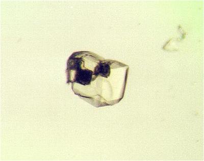
These two images were taken from http://srs.dl.ac.uk/OTHER/NEWSROUND/Issue_10/px10.htm to illustrate the potential power of crystal annealing:
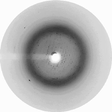 Before | 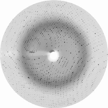 After |
The URL above has subsequently vanished but apparently a paper has been published on this observation: Ells, Antonyuk & Hasnain, Acta Cryst. (2002). D58, 456-458.
Cryocrystallography on proteins was pioneered in the early days by the likes of Hakon Hope and Ada Yonath who did extensive work on extremely difficult projects like the ribosome, [see Hope, H. (1988): Cryocrystallography of Biological Macromolecules: a Generally Applicable Method. Acta Cryst. B44 22-26] and whose contributions in using a method that we now take for granted should not be overlooked. Gregory Petsko had done pioneering work prior to that on protein crystals at sub-freezing temperatures in flow cells for the purposes of studying enzyme reactions, but this did not involve collecting data at liquid nitrogen temperatures. More recently Elspeth Garman has been doing a lot of research into cryo-protection and especially radiation damage.
The earliest attempts at cryo-crystallography involved picking up oil-covered protein crystals mounted on small glass spatulae or pitch-forks and was particularly time-consuming and cumbersome. However the most frequently used method of cryo crystal mounting used today is the fiber loop method which was popularized by Teng [see Teng, T.Y. (1990): Mounting Crystals for Macromolecular Crystallography in a Free-Standing Thin Film. J. Appl. Cryst. 23 387-391] in the early 1990's. The setup is deceptively simple, consisting of a magnetic base, a metal pin and a fiber loop secured to each other by epoxy glue. Hampton Research has made a lot of money selling kits to make these loops - see their array of cryocrystallography equipment. Hampton have also done an excellent job of standardizing hardware so that going to synchrotrons with exotic loop bases is now largely a thing of the past.
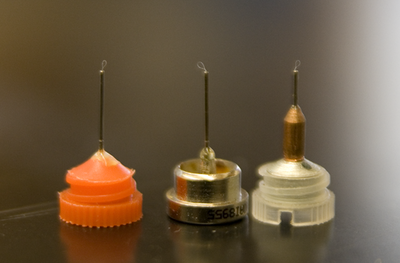 Hampton Research's CrystalCap, CrystalCap HT and CrystalCap Copper bases with mounted cryo loops. Note the tab slot in the right-hand cap. |
 Basic setup is the cap, pin, loop and associated cryo vial |
The simple set up involves a magnetic cap (attaches to goniometer head on the X-ray machine), a thin metal pin and a thin fiber loop of variable size (0.05-1.0 mm, typically). Pins are glued into the bases with epoxy (Hampton sells mounted cryoloops). The caps fit on fairly standard magnetic bases (see which attach to or are integral parts of existing goniometer heads. Hampton's Crystal Cap HT is my current favorite since this works especially well with the NSLS X29 and X25 beamline goniostats. Previously the standard Crystal Cap and Crystal Cap Copper were my standards. The "copper" version helps to reduce icing on home sources because of the greater heat transmission by the copper sleeve but it's not compatible with the cryo tongs so routine application is somewhat limited. Icing on the pin is a relatively rare problem at synchrotron beamlines due to the short duration of data collection. The associated cryo vial serves as a reservoir for liquid nitrogen when handling and transporting frozen crystals. Vials attach to the bases either via screw mounts or via magnets. Most of the robots for auto-mounting at synchrotrons have converged on a standard of Hampton mounts (usually the low profile all-metal HT mounts, shown center in the figure above) with a base to loop distance of approximately 21mm (e.g. see the X6a Wiki for the automounter). The loops are made of 20µ or 10µ nylon thread - typically we prefer the 20µ kind which seem to be less likely to move ("wave in the breeze") in the cryostream.
The early 1990's saw gradual acceptance of the method as generally applicable, including dispelling concerns that it would distort the protein structure or introduce excessive non-isomorphism. Many crystal structures e.g. the CDK2:CyclinA structure from the early days of the Pavletich lab would have been completely impossible without it as the crystals died overnight on the comparatively weak home source at 4 deg C. During that era cryo crystallography became the standard method for macromolecular data collection.
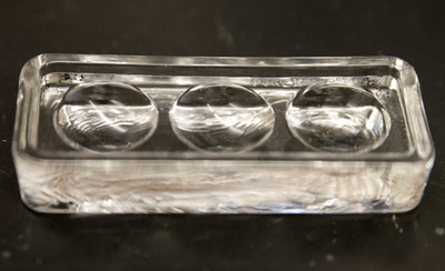
Three well Pyrex dish, commonly used in crystal manipulation
Typically if I am preparing a crystal for data collection I do the following:
All of which is a lot easier to type than it is to do. People typically experience a lot of problems manipulating crystals. Crystals may form on and stick to cover slides. If you cannot "squirt" them off you are going to have to use some sort of tool (small, sharp object) to gently push the crystal until it breaks free. Or crumbles, if you are unlucky. Hampton make a convenient set of Micro Tools that work for this purpose but there's nothing stopping you from improvising your own. Many xtals can be persuaded to become free-floating using this approach. Use only the minimum force necessary, and apply the force only to the end/edge of the crystal. Crystals that stick to the surface of the drop can sometimes be induced to become free-floating my directly pipetting a few µl of solution directly on top of the crystal and "submerging it". In more extreme cases you can push on one end of a crystal to get it to slide off the surface into the body of the drop if it is just held there by surface tension. In bad cases crystals will grow on the skin on the surface of the drop which nearly always requires you to do some controlled violence to get the crystal off the skin. Be patient. Be gentle. Attack these crystals at one end, not in the center of them. Beware of the skin getting stuck to your tools and pippette tips. If you can remove the skin and keep your crystals, so much the better. Mangled crystals do not diffract, no matter how "important" the project is. Also in some cases careful use of a tool can remove small satellite crystals from the surface of a larger crystal, mainly when they "stick out" from the edge or surface of the crystal. In 19+ years of protein crystallography I have not found a way to separate extensively intergrown protein crystals without mangling them. Unless your crystals are exceptionally robust, you're not going to either.
Remember: the less physical contact involved with your crystal, the better it will diffract.
Fishing the crystal out of the cryo solution with the loop can be a maddening and frustrating experience. Practice relaxation exercises. Practice on other crystals. Try to draw the crystal to the surface of the solution using viscous flow (move the loop near the crystal, but don't drag it to the surface with the loop). When the crystal is close to the surface move the loop so that it passes around the crystal, while pulling the loop out of the drop slowly. If your coordination and timing is OK, the crystal gets drawn up into the loop by surface tension and remains there by that same tension. If your timing is bad, the crystal is either stuck to the metal pin (very bad) or still in the solution (you can try again, and again, and again). Crystals that float are easy. Crystals that sink are murderous and you may have to literally haul that sucker out of the solution with the loop if it sinks too quickly. Avoid that if possible, but I have done it this way more than once. Conditions containing iso-propanol (bad) or ethanol (very VERY bad) will drive you nuts as the convection currents caused by evaporation make the crystal swirl around and spin on the solution surface. It's fun, trust me.
Freezing in situ, as described above, freezes the sample as it is placed on the goniometer head of the X-ray machine. As the loop enters the 100K nitrogen gas stream it freezes quite quickly as long as it goes into that stream once and doesn't waggle in and out of it. Check the alignment of the nozzle and pre-center the loop before you start. As an alternative you can simply plunge the crystal into liquid nitrogen and then store the crystal in a cryo cane for future use. It is important to use fresh lN2 since it grabs moisture out of the air quickly and ice swirling around in the lN2 can easily embed in your cryo solution as it freezes. In order to take these pre-frozen crystals and put them on the beam you need to use an array of apparatus:
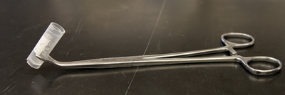 |
Forceps for holding the cryo vial under liquid nitrogen |
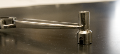 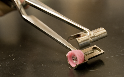 |
Cryo tongs allow a crystal to be removed from a goniometer head. The tongs must first be cooled to
liquid nitrogen temperature, then quickly clamped around the frozen crystal before the whole
crystal+tong ensemble is plunged back into liquid nitrogen before anything can thaw. It works most of the
time. The head of the tongs is a split metal block with a milled indentation that lets the crystal sit inside
the cold block away from the warm air.
Home systems with inverted Phi axes, and synchrotrons with flexible goniostats often obviate the need for cryo tongs because you can recover the crystal straight into the cryo vial. |
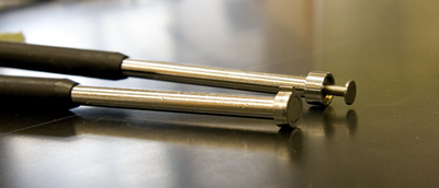 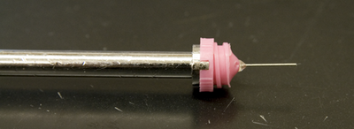 |
Cryo "wands" plug into the bottom of the caps. For the standard CrystalCap (incl the Coppers) the bases have a locator tab that allows the wand to fix in place and unscrew the cap from the threaded vial. The magnetic HT bases don't have tabs, so the wand has an internal plunger mechanism to displace the cap from the wand. A close-up of the CrystalCap in place on the wand (with the tab located) is shown in the second picture. |
 |
Cryo canes are thin aluminum storage canes, in version with and without tab stops on them, that can store 1-5 crystals. The ones without tabs are best for putting a lot of crystals on canes. Usually more than 4 runs the risk of the top one being thawed so the best crystals should always go at the bottom. |
Similarly the protocol for removing a crystal from (e.g.) a home source for relocation to a synchrotron is:
For obvious reasons, fresh lN2 with no ice is important for both steps, as is dry apparatus (ice will form on tongs left to warm up in air). Ethanol is a pretty good way of displacing ice. A certain amount of practice is necessary to get the manual manipulation aspects working fast enough without inadvertently removing the crystal from the lN2 (which guarantees disaster via icing and rapid thawing).
At X29, X25 and probably some other beamlines their cunning design of their goniostat enables you to mount pre-frozen crystals straight from lN2-filled vials right onto the goniometer head. This has saved us a LOT of time at these beamlines.
|
Sealed tubes: small molecule crystallographers are in the enviable
situation of not needing as many X-ray photons to get a good signal from
their crystals. For many applications a sealed tube generator gives
them enough intensity. The entire X-ray generation system is sealed into one
unit, thus eliminating the need for vacuum pumps, motors to spin the target
etc. The system is therefore very compact and easy to maintain. The tube
is still water-cooled to dissipate heat. Most sealed tubes are lower power
to avoid overheating the target. Rigaku/MSC makes a 3 kW
sealed tube generator
that is targeted toward small-molecule work, for example while our rotating
anode runs at 5 kW.
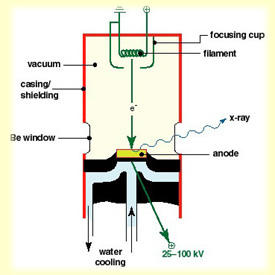
A large potential difference (50kV or so) is put between a filament (cathode) and a metal target (anode). The filament is electrically heated, and the electrons that are excited out of the conduction bands "boil off" the filament, accelerate down the tube under the potential difference, and smack into the target. When they do so, they ionize electrons from the target material. When these (or other) electrons drop back into these vacated energy levels, they give off energy partially in the form of electromagnetic radiation. Plus a lot of heat. If the electrons are ejected from the lowest-energy orbitals (1s, 2s etc) then a lot of energy is released when electrons reoccupy them - released as X-rays. Metal targets are used because these do not damage much with electron bombardment and conduct heat efficiently (most of the energy is lost as heat, not X-rays). Beryllium windows, relatively transparent to X-rays, let the X-rays escape the evacuated tube. |
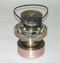 | Rotating anodes: these are the same idea as a sealed tube, except the anode is spinning (e.g at 6,000 rpm), allowing a much greater loading to be put on the target since the heat is spread out over a larger area. Other than that the differences are purely engineering: a 2 lb copper target spinning at 6,000 rpm places some stress on bearings and seals; the vacuum system is no longer a single assembly and typically has two different pumps; wear and tear is significant and maintenance becomes a more serious issue. The state of the art for macromolecular rotating anode sources is the Rigaku/MSC FR-E generator which is a lower power but high brilliance X-ray generator. |
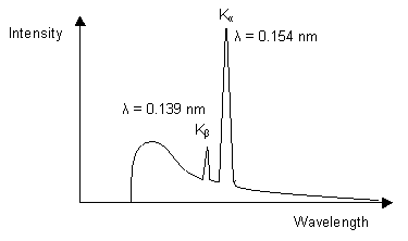 |
In both sealed tube and rotating anode sources the wavelength is fixed by the characteristic emission spectra of the target material. Copper is the one most often used for proteins since it is hard, an efficient conductor of heat, and the CuKα emission is relatively intense. The wavelength of the X-rays produced is 1.54 Å. Small molecule crystallographers typically use weaker Molybdenum sources, with a wavelength closer to 0.7 Å, since the higher-energy X-rays are absorbed less by the experimental mount, etc. |
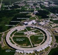 Synchrotrons:
macromolecular crystallographers have increasingly
hijacked the high-energy physicists' toys to use them as ultra-bright
X-ray sources. Synchrotrons are large tubular rings under high
vacuum in which fundemental particles (usually electrons and positrons)
zoom at velocities near the speed of light. The "rings" are really
just polygons, since relativistic particles are kind enough to obey
Newtonian physics in at least some regards. The positrons/electrons
travel in straight lines until forced to turn a corner by powerful
magnets at the vertices of the polygons.
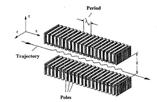
At these beam bending magnets, some interesting things happen. It costs energy to deflect (change the momentum of) all those particles. That energy gets returned to us in the form of intense electromagnetic radiation when the particles change direction (velocity). A lot of this radiation is in the X-ray band, and we can use it as a remarkably powerful X-ray source. Even more powerful X-ray sources can be formed if one puts insertion devices in the straight stretches of the particle beam. Wigglers and undulators make the beam do just that - wiggle up and down. Since the velocity is changing, electromagnetic radiation is produced but these devices are designed to produce a lot more local deviation in the trajectory (before returning to it's original path) so wigglers and undulators act as X-ray sources much brighter even than bending magnets. A typical undulator is engineered to extremely high tolerances, features superconducting magnets, and is a few meters long.
The primary synchrotrons within the USA are: the National Synchrotron Light Source (NSLS) at Brookhaven National Lab; the Advanced Photon Source (APS) at Argonne National Lab; the Cornell High Energy Synchrotron Source (CHESS) at Cornell College; Advanced Light Source (ALS) in Berkeley; Stanford Synchrotron Radiation Lab (SSRL) in Stanford California. Other notable ones include Diamond (UK), ESRF (France), Photon Factory (Japan) etc - consult synchrotrons of the world for a fuller list.
Bending magnet beamlines at Brookhaven (NSLS) are 50-100x brighter than a home source (e.g. X12C, X9A). Wiggler beamlines at Brookhaven (e.g. X25) are about 10x brighter than bending magnet beamlines. At Argonne (APS), the bending magnet beamlines are at least 1000x brighter than a home source and the undulator beamlines are 10-100x brighter than the bending magnets. The actual brightness, beam shape, wavelength tunability and other factors are all heavily dependent on the design of the beamline optics as well as the synchrotron itself. Nearly all modern beamlines have optics with energy resolution and energy tunability properties suitable for MAD data collection (CHESS A1 and F1 beamlines are notable exceptions).
Nickel filters: In the case of rotating anode generators, the spikes in the radiation output correspond naturally to (e.g.) Copper Kα radiation and we choose the brightest spike. The adjacent weaker Copper Kβ radiation can partially be removed by using a Nickel filter. (Kβ is absorbed rather well by the next element up in the periodic table, it turns out). Nickel filters are only useful on Copper anode home sources. Monochromators: Monochromators are basically putting a diffraction experiment before your diffraction experiment. At a home source, a mosaic chunk of graphite is illuminated by your X-ray source. It undergoes diffraction. The graphite is oriented in such a way that a very intense, low resolution reflection is in diffraction condition. Since diffraction angle depends on wavelength (λ=2dsinθ) a small pinhole on the far side of the apparatus can effectively select a limited range of the X-ray spectrum. Monochromators have been surpassed by mirrors and multilayer optics at home sources, but at synchtrotrons they are a central component of beamline optics, using the same principals (but using much larger silicon or diamond crystals).
Mirror Systems: At low angles, X-rays display "total reflection" from mirror surfaces. This is not a 100% efficient phenomenon so one ends up with a transmitted and reflected beam. If one bends the mirror then one can obtain some focussing of the reflected beam, either allowing one to use more angular range of the incoming X-ray beam or to make the outgoing reflected X-ray beam convergent on a specific point on the apparatus. Typical mirror setups for home sources use elongated Nickel- or Platinum-coated mirrors (to absorb CuKβ) in the horizontal and vertical planes. Although long mirrors (e.g. the Yale design) are usually more intense than monochromators, the spectral purity of these systems is quite mediocre, since there is no mechanism to get rid of the "white radiation" background and the CuKβ is only partially absorbed. Mirrors are used at synchrotrons for beam focussing only, with wavelength selection achieved using separate monochromators. Mirrors on home sources usually have better-defined beams (smaller) than the corresponding monochromator optic.

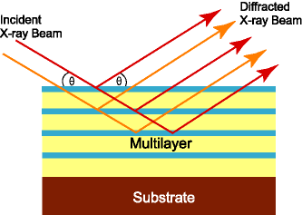
Collimators: these are just pinhole devices to reduce X-rays, which might otherwise propagate in all three dimensions, into a thin controlled beam. Typical collimators are just metal tubes with two aligned pin-holes at each end. The pin-holes usually have diameters in the range 0.1-0.3 mm. Collimators do not change the spectral purity of the X-rays they are just a physical device to limit the beam by basic geometry. On mirror systems they mainly serve as a device to limit air-scatter by the beam from reaching the detector. On a synchrotron they do tend to clip the edges of the beam and we tend to see better results from smaller (0.1) collimators than larger ones.
Vendor websites
Properties of ideal X-ray Detectors :
Geiger counters: everyone knows that Geiger counters can count X-rays via ionisation events. They can do it pretty well, within certain limits. In fact older diffractometers counted one reflection at a time using this ionisation chamber technology, and if your crystal lasted long enough one got very good data indeed. Collecting a 250,000 reflection dataset one reflection at a time will take you a while, which is the whole reason area detectors were invented.
Multiwire proportional counters: these extended the ionisation chamber idea - these were some of the first true "area" detectors, and were part of the wave that revolutionized protein data collection in the 1980's. The Xuong-Hamlin (UCSD) model was the first one that was used for routine data collection. These detectors contain a 2D grid of wires in a medium that was ionised by X-rays. The ionisation events are detected as electronic signals on pairs of wires in the x and y directions, producing a 2D electronic image of diffraction. The most popular of these detectors was the Xentronics/Nicolet/Siemens detector, still in use in some labs today, and also the older Xuong-Hamlin UCSD design detectors (the original ADSC detector). Multiwire detectors cannot deal with high flux, however (their ionisation medium saturates, as does the detection circuitry), so they were not effective a synchrotron sources, and even for well-diffracting crystals on home sources (e.g. lysozyme).
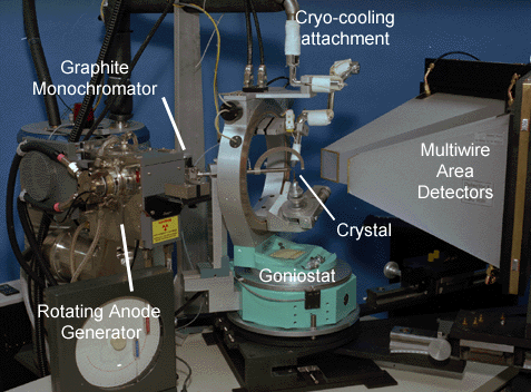
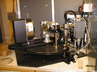
Ionisation type detectors literally count photons in a serial manner - so-called photon counting detectors. The remaining detector technologies "integrate" the signal by accumulating the counts to be read out later.
Film: if you've ever left high speed photographic film in checked-in luggage you'll realise that X-rays fog film. Film was the first X-ray recording medium (Roentgen ~1895), and was commonly used at places like synchrotrons up to about 15 years ago. Film suffers from a limited dynamic range, a fair amount of background noise (chemical fog) and principally that it's a pain to develop and scan all those images. Film generally has higher spatial resolution than most image plate detectors but newer CCD detectors get close. Most modern CCD and image plate detectors usually offer more active area than the old film packs did (12x12cm ?).
Image plate detectors: Image plates (storage phosphors) arose as popular alternatives to film in medical labs - X-ray photons cause charge to accumulate in Europium-doped matrials that coat these flexible plates. The metastable charge can then be read out by photostimulated luminescence with a laser. The image plates are then "bleached" with white light before re-use to remove any remaining signal.
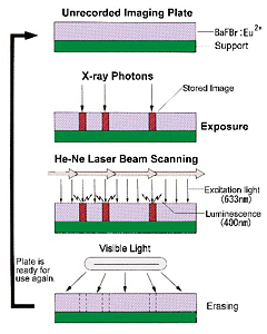
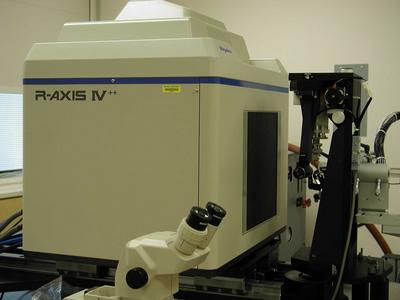
Image plates are larger than most other area detectors, fairly sensitive, have a large dynamic range. The R-AXIS and MAR detectors came to dominate (and still dominate) home source data collection. The R-AXIS series of detectors utilize two plates, so that one plate may be read while the other one is being exposed. The R-AXIS IIc has smaller rigid plates, while the R-AXIS IV and IV++ have flexible plates mounted on a steel belt.
 |
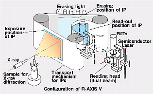 |
| The familiar Raxis-IV image plate area detector | Schematics of R-AXIS IV operation |
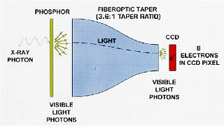
CCD detectors: CCDs are small light-sensitive computer chips that are used extensively in modern digital cameras (and spy satellites). In X-ray detectors, the X-rays first strike a gadolynium oxysulfide phosphor screen at the front of the detector, the phosphor image is reduced in size by a fibre-optic taper then projected onto the CCD chip. The taper is necessary in order to increase the active area of the detector over the rather modest size of the CCD chip itself (most CCD chips are of the order of 1-5 cm). The very first version of this for routine use in crystallography was the FAST detector by Enraf-Nonius.
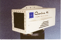
Good CCD chips (as opposed to the junk in most consumer digital cameras) are expensive to make, especially the larger ones, so many CCD detectors comprise several small 1 or 2 megapixel (1K x 1K pixel = 1 megapixel) CCD chips stacked side-by-side. The most popular one is the ADSC Quantum210 with four 1 megapixel chips in a 2x2 array. ADSC now also make a 3x3 array of 4 megapixel chips (2K x 2K), the Quantum315. The Quantum315 is on the X25 beamline at NSLS and on most APS/Argonne beamlines, while the Quantum210 is on CHESS A1 and F1. CCDs are sensitive, but suffer from electronic noise (they must be cooled to reduce this) and are sensitive to environmental radiation (the so-called "zingers") including radiation originating in the fiber-optic taper. Their dynamic range is only moderate, a deficiency most often exposed at synchrotron sources where low-resolution reflections can become saturated on longer exposures ("overloads").
Newer technologies: Crystallographers tend to use whatever technologies have been developed by others: multiwire photon counters were developed by high-energy physicists, image plates for radiology, CCDs for spy satellites and digital cameras. New technologies like Pixel Array Detectors (using the photoelectric effect) and Amorphous Silicon Detectors will probably filter their way down as X-ray crystallography detectors once they become more widely available. MAR appear to be developing detectors based on solid-state semiconductors that detect X-rays directly. GE are doing the same. So far these do not seem to have penetrated the market and the image plate detectors still dominate home sources, as do the CCD detectors for synchrotrons.
Why do we use CCD detectors at synchrotrons?: they are relatively sensitive area detectors with a resonable dynamic range, fast readout time, and reasonable active area. Although they have a smaller area than a typical image plate (the Q315 is, however, large), the much faster readout time (less than 10 seconds vs. ~2 minutes) is an enormous advantage at a synchrotron, where exposure times are typically 5-40 seconds and the amount of dead time between exposures is a huge factor in data collection efficiency, often exceeding exposure time at the newest synchrotron sources.
Why do we use image plate detectors in house?: Image plates are large, sensitive and have a large dynamic range. In fact their only significant problem is that they take a relatively long time to read out (2-4 minutes with Raxis IV, IV++). This isn't a big issue with in-house data collection where exposure times are 15-60 minutes an image. CCDs are less useful in-house: they are more sensitive than image plates, but they also suffer with much more inherent noise than image plates for the same exposure time (from both zingers and electronic noise). For weakly diffracting crystals on modest intensity sources, image plates tend to give better data.
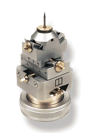 Huber goniometer head
|
Your crystal is mounted onto a small precision goniometer head that allows for precise adjustment of the translations (and in some cases limited rotation via arcs) of the crystal. On most beamlines this is what you use to center the crystal. On some newer beamlines there is now a separate centering mechanism so you don't need to do that. Supper also offers goniometer heads with detachable extended arcs for easier mounting of pre-frozen crystals as an alternative to cryo-tongs. |
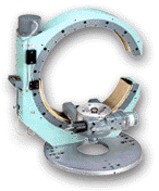 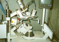 |
The mechanism that the goniometer head attaches to is called the goniostat and these are designed to allow precise positioning of the centered sample at a wide array of positions. Some goniostats are simple 1-circle designs (like the one on our area detectors) with a single φ (phi) axis. Other more elaborate ones may consist of a large circle on which the rotation axis may be positioned arbitrarily around a circle, as shown at left. These are the 3- and 4-circle goniostats, of which the majority are made by the Huber company in Germany. The various angles tend to be φ, χ, ω, 2θ. You most often see these at synchrotrons since they are both expensive and large, although also versatile. A more compact design that still allows much flexibility is the kappa goniostat by Enraf-Nonius that has a specific inclination of the κ axis to the φ axis to allow for a relatively large range of accessible crystal angles with relatively small bulk. Normally the detector is arranged such that the direct beam would strike the detector approximately at its center - the 2θ axis on many gioniostats allows the detector to be offset from the beam and is especially useful when trying to collect high resolution data on small detectors or large unit cells (when the detector has to be moved further back). |
There's also the cryo unit. These come in two basic designs - those that use liquid nitrogen and those that use nitrogen gas as the main source. The simplest design is simply source of dry nitrogen gas (via boil-off) that is cooled by passing it via a metal coil through a liquid nitrogen dewar and is then blown at the crystal. The very first Rigaku/MSC systems were like that. The Oxford cryostream system such as the one at Princeton uses a different method - it sips lN2 which it then heats to room temperature gaseous form for flow control before cooling it back down (via heat exchange from the incoming lN2) to 100K and blowing it at the crystal. Lastly the X-STREAM and X-STREAM 2000 systems from Rigaku/MSC purify their own N2 gas from the air, and then cool it via a helium refigeration pump. All systems use a laminar coaxial flow of room temperature dry nitrogen surrounding the core of cold nitrogen gas to reduce sample icing via mixing with room air.
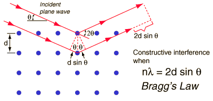
The single, critical, thing that Bragg's Law imparts is as follows: scattering from a crystal occurs in all directions. However the scattering is only visible in a finite number of directions that obey the above law, i.e. the path difference between waves scattered by adjacent lattice planes is a multiple of the wavelength of the radiation - the waves are in phase and constructively interfere.

The reciprocal space unit cell axes have defined directions with respect to their real space counterparts (a, b, c). Namely, a* is perpendicular to the plane containing b and c. (b* perpendicular to a/c; c* perpendicular to a/b). These are geometric consequences of the Laue conditions.
Bragg's Law describes the requirement for diffraction in algebraic form. The diffraction vector translates Bragg's Law into a 3D vector whose direction is linked to real space unit cell axes - now we have a directional description of the diffraction process. The Ewald construction shows this equation in graphical form, integrating the scalar (Bragg) and vector (Miller index) description of the diffraction process, and allows us to visualise diffraction.
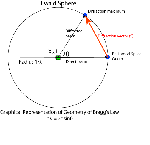
There sphere has a radius of 1/λ. The crystal sits at the center of the sphere. In the diagram above the X-ray beam comes from the left. The unscattered (direct) beam passes through the crystal and the point where it reaches the sphere surface is the origin of reciprocal space. For a diffraction point in reciprocal space to be in diffraction condition, it must lie on the surface of the Ewald sphere. The angle between the indident and diffracted beams is 2θ and the vector connecting the reciprocal space origin and the diffraction point is the diffraction vector.
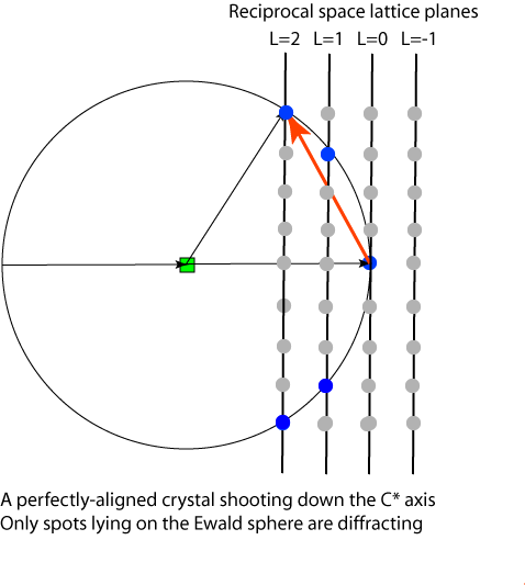
Visualization of the Ewald sphere construction is useful in data collection because it gives a way to understand which points are in diffraction condition. In the diagram below a "prefectly aligned crystal" is arranged such that the C* axis is pointing down the C/C*-axis, and that the reciprocal lattice planes are pependicular to the beam. Lattice points are shown in gray, and those in diffraction condition are shown in blue.
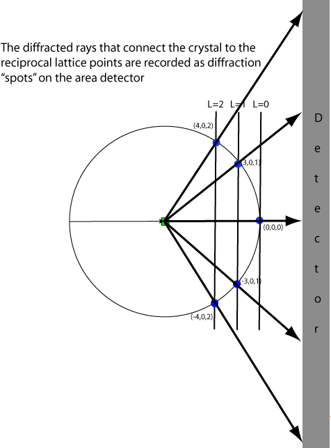
Even though the Ewald sphere is in reciprocal space (inverse distance) and detector geometry is in real space, we can use the predicted angles of diffraction (2θ) to predict the diffraction pattern measured by a by a detector given a known instrument geometry. We do this based on ray-tracing or similar triangles.
Since reciprocal space can be viewed as consisting of planes of reciprocal lattice points, the diffraction pattern appears as if it is comprised of diffraction spots arranged on a series of ellipses. For the perfectly aligned crystal the rings are all circular since the planes are perpendicular to the beam. Notice that the L=0 plane doesn't show up on the pattern in this situation because only the (0,0,0) reflection is in diffraction condition and is buried underneath the beam stop. Note that (0,0,0) is always in diffraction condition but we cannot measure it directly because it is swamped by the X-rays in the direct beam that did not interact with the crystal.
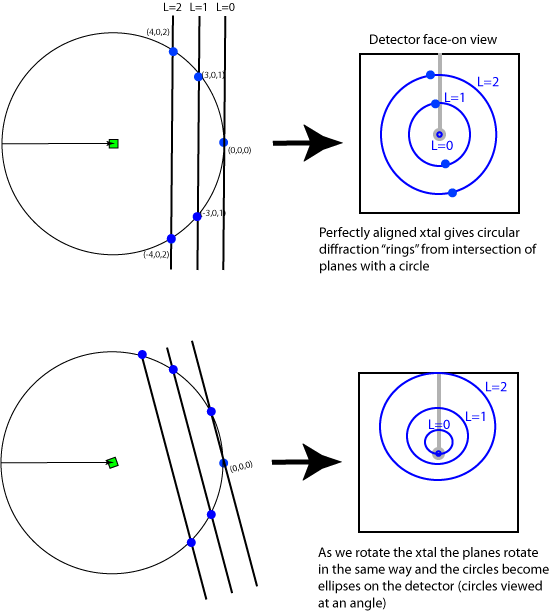
As the crystal rotates, the reciprocal lattice rotates in the same way as the crystal and the planes become inclined to the direct beam (which is usually the viewing angle). The projection of the circles onto the detector renders them as ellipses. Also notice that since the planes are now inclined, more of the L=0 level is visible on the detector and that different parts of the L=1 and L=2 planes are in diffraction condition.
| Oscillation (Rotation) | ||
|---|---|---|
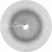 |
The physics of oscillation images are relatively easy to understand, since all they involve is rotating the crystal through a small solid angle about a single axis. The pattern you see corresponds to planes in reciprocal (diffraction) space slicing through the Ewald sphere so that only a limited amount of each lattice plane is in diffraction condition within the oscillation range. Entire datasets are built up by collecting contiguous series of such images to form a solid volume of rotation. This is the method that we use to collect all our data. This is variously know as the "rotation method" or oscillation method. The ability to auto-index oscillation data has considerably enhanced the usability of this method. | |
| Weissenberg | ||
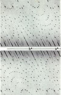 |
Weissenberg data collection combines the rotation/oscillation method with a coupled translation along the rotation axis. This is used to reduce the overlap of spots that can occur with larger oscillation ranges or larger unit cells. In practice you need to align your crystal accurately in order to make the most of Weissenberg photography and data collection is rather tedious and the diffraction pattern more difficult to interpret. Weissenberg cameras are cylindrical drums. At one point a beam-line at Japan's Photon Factory used this method to collect protein data, but that's probably no longer the case. | |
| Precession | ||
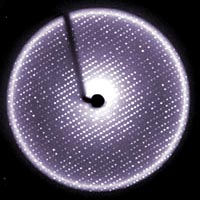 |
As the name suggests, precession photography involves making a crystal precess at a fixed angle around a defined axis. If the crystal is precisely aligned such that a real space unit cell axis lies along the rotation axis, a precession photograph can be arranged to provide view of a single plane through diffraction space. Since this involves introducing a metal layer screen that blocks most of the diffraction that is happening and only allows passage of that from the desired layer, it is an incredibly inefficient way of collecting data. However it was used in the early days of protein crystallography before advanced algorithms for auto-indexing oscillation photographs made the interpretation of those more straightforward. I did a lot of precession photography when I was screening for heavy atom derivatives as an undergraduate (1986). The Pavletich lab bought a precession camera in 1993 but it was never installed. That should tell you something. The method produces an undistorted view of a single reciprocal lattice plane. In the (very) old days you used to compare zero-level projections (0kl, h0l, hk0) between natives and potential heavy atom derivatives to look for relative intensity changes. These days you can do the same thing in a fraction of the time using conventional oscillation photography. | |
| Laue (polychromatic) | ||
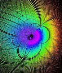 |
In contrast to methods that have been discussed before, all of which use monochromatic X-rays, Laue photography specifically uses polychromatic X-rays over a wide wavelength range. This is the same thing as if you made the Ewald sphere more like a solid ball than a thin shell like a ping-pong ball. The advantage of Laue is that many, many diffraction maxima are in diffraction condition at the same time, so we can collect the data in one or just a few images. Laue data collection held promise in the early days, especially for high-symmetry space groups and time-resolved studies, but the inherent difficulties in indexing the diffraction images from these systems, with multiple overlapped spots from multiple wavelengths, has essentially rendered it useless for routine data collection. In fact very few Laue-capable beamlines are in routine operation. | |
Usually, what you're faced with is working at the low-resolution end. Experience suggests that you can get meaningful biological data from structures at 3.5 Å resolution or better, but at worse than 4.0 Å you better either have another very similar structure for comparison, or be working on something of epic importance (e.g. the ribosome). At 4.0 Å the conformation of most side-chains will be questionable, and it will not be possible to trace your chain without ambiguity in many cases - the biological information content of your structure starts to become pretty low.
Sometimes you can extend the resolution of your crystals by going to a brighter source. Very small but well-ordered crystals may not diffract well in the lab because the beam is not very bright and it is quite large. Put these crystals in a synchrotron beam and they often yield very good data at relatively high resolution. Conversely, large badly-ordered crystals will often diffract as badly at the synchrotron as they do at home, because the strength of the X-ray beam is not limiting the resolution of the data - the crystal order is.
The number of unique reflections in a dataset varies as the cube of the resolution - specifically, as 1/d3. This means there are 8 times more diffraction data points at 2Å than at 4Å. Apart from the sheer advantage of increased optical resolution, having 8x more points in your refinement alone will pretty much guarantee a much greater degree of accuracy in your structure.
Each diffraction pattern contains symmetry. The number of symmetry operators in the real space lattice (excluding those by centering operations in C, F and I lattices) gives the number of symmetry-related reflections in reciprocal space. However Friedel's Law may double that number....
In the absence of significant anomalous scattering even the lowest symmetry space group P1 has two-fold redundancy in complete data by Friedels Law:
I(h,k,l) = I(-h,-k,-l)
Assuming that Friedel's Law applied, this is the redundancy you expect from collecting an entire sphere of diffraction data:
| P1 | 2 |
|---|---|
| P2, P21, C2 | 4 |
| P2x2x2x, C2x2x2x, F2x2x2x, I2x2x2x | 8 |
| P4x | 8 |
| P4x2x2 etc | 16 |
| P3x, R3 | 6 |
| P3x21, P3x12, R32 | 12 |
| P6x | 12 |
| P6x22 | 24 |
| P2x3, F23, I2x3 | 24 |
| P4x32, F4x32, I4x32 | 48 |
A mostly complete sphere of data can be collected on any crystal by rotating the crystal through 180 degrees solid angle. You don't need to go to 360 because the leading edge and trailing edge of the Ewald sphere are collected at the same time either side of the beam stop. If you have offset the detector (in 2θ) to collect higher resolution data you may need to collect more than 180 degrees of data to compensate for this. If you lose data due to overloads and overlaps you may need to collect yet more data, often a low resolution pass at reduced exposure time (and larger oscillation angle) over the same solid angle - often the case with strong diffractors on CCD detectors at synchrotrons. A small amount of data will be lost in the so-called blind region due to the curvature Ewald sphere: and lies along the rotation axis in a curve bi-conical shape. This region is often effectively collected elsewhere by virtue of crystallographic symmetry (except in the case of space group P1 where you need to re-orient the crystal to collect this data). Reflections that lie close to the spindle (rotation) axis also have a high Lorentz correction and often cannot be estimate reliably.
If the highest symmetry axis in your crystal is N-fold, then the minimum number of degrees you will need to collect is 180/N. This is the minimum value - if your crystal is in a non-optimal orientation you will need to collect more data. Theoretically, the best orientation is with the highest symmetry axis almost aligned with the rotation axis of data collection. The worst orientation is with it aligned perpendicular to that axis.
Even within this proviso, if you don't start at the right point, then you can end up collecting the same data twice e.g. in orthorhombic with 90 degrees of data you may end up with complete data, or with half the data collected with twice the redundancy depending on your start point. From the practical standpoint the other symmetry elements may allow you to accumulate this "missing data", and in orthorhombic you can often get away with only 70 degrees of data for well-oriented crystals.
Assuming you already have the highest symmetry axis point along the rotation axis, the right place to start would be shooting down one of the other symmetry axes. The direct beam bisecting the symmetry axes is usually the worst place to start. Processing the data during data collection, and taking a hard look at the Scalepack log file, is also a good way to monitor if you are collecting data in the best way.
As a practical matter, some reflections that lie near the rotation axis are often "thrown away" due to large Lp corrections. The Lorentz correction (L) is a correction for the amount of time that a reflection spends in diffraction condition. For reflections lying near the rotation axis this correction may be very large and small variations in the estimation of this factor may introduce large errors into the intensity estimate. For the same reason, you expect reflections that are furthest from the rotation axis to be relatively weaker because they pass through diffraction condition (Ewald sphere) the fastest and spend the least time diffracting. This also tends to be correlated with high resolution data, which tends to be weaker anyway.
The polarization correction corrects for the differential scattering of X-rays when the incident X-rays are polarized. The form of the correction takes various forms, but (e.g.) for a circularly polarized beam the correction is: p = (1 + cos22θ)/2. At a synchrotron the polarization is mostly in the plane of the synchrotron ring, which means that reflections whose diffraction vectors are mostly perpendicular to this plane benefit the most from the polarization (intensities enhanced) - diffraction is strongest in the directions perpendicular to the polarization plane. This is the reason that the oscillation axis at synchrotrons is horizontal because those reflections that are passing the fastest through the Ewald sphere (therefore lower intensities recorded) experience the most boost from the polarization effect. The Lp correction issue is also why it is often useful to have the highest symmetry axis close to but not precisely aligned with the rotation axis in order to capture this "blind region" data via symmetry relationships (if it is perfectly aligned then reflections related by this axis are still in the blind region).
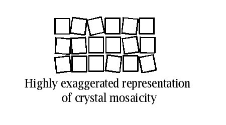
The estimate of mosaicity is often convoluted with the intrinsic beam divergence (the angular discrepancy from "perfectly parallel"). So on a home source, with a more divergent beam, one is lucky to get less than 0.3 degrees for net crystal mosaicity. On a synchrotron beamline with a nearly parallel beam I have seen as low as 0.12 degrees from a frozen crystal. But I've also seen something close to 2.5 degrees on very ill-behaved crystals.
Note that it is perfectly possible to collect data on crystals with moderately high mosaicity as long as you take into account the fact that overlaps are more likely (reflections persist over a larger angular range, so frames get more crowded). I recommend that frame sizes should be at least the same size as the crystal mosaicity to avoid splitting up the reflections over too many frames (although something like 2/3 of the mosaicity is the real lower limit). Empirically higher mosaicities tend to be associated with crystal damage during handling or intrinsically poor crystal order.
Mosaicity is sometimes anisotropic, which can cause problems during data collection although you can refine a per-frame mosaicity in Denzo and Scalepack. Often times, however, this just seems to model undesirable behavior like spot blurring due to anisotropic crystal disorder, and its not always desirable to let the mosaicity fluctuate in an uncontrolled way during data processing.
The 1.0 degree frame size is a compromise. Ideally we would only accumulate data at a pixel when there was a reflection contributing to the pixel. This idea was implemented as thin phi-slicing on the older FAST and XENTRONICS area detectors that had fast readout times. Image plates have had relatively slow readout times until recently and so 0.1 degree frames had proven impractical even on home sources. Thick frames would increase the ratio of "full" reflections to "partial" reflections, but in addition many pixels on the detector would spend as long accumulating background noise as they would recording a spot in diffraction condition. Low resolution reflections pass through the Ewald sphere "slower" than the high resolution ones and so tend to have a higher partial/full ratio.
In addition, as frame size increase so do the chances that reflections passing through the Ewald sphere will overlap each other within a frame. These overlaps are rejected by the processing software. The volume of the reciprocal lattice passing through the Ewald sphere for a fixed frame size increases with resolution, so overlaps tend to occur more with high-resolution data than with low-resolution data. To a certain extent overlaps can be minimized by choosing a minimal "tight" integration spot size in Denzo. They can also be reduced by moving the detector further away from the crystal (spreads the diffraction pattern out). However unless you are using a large detector, moving it back will also reduce the maximum resolution recorded at the edge of the detector. Overlaps can also be reduced by reducing the frame width (but pointless below 2/3 of the mosaicity) or sometimes by using a smaller collimator to reduce the illuminated volue of the crystal.
The typical practical range of exposure times for frozen crystals:
Radiation damage manifests itself as a loss of order within the crystal, leading to reduced diffraction strength and reduced resolution. This shows up as an increased per-frame B factor during scaling. The phenomenon arises via two mechanisms: dose-dependent in which X-ray photons ionise the protein and directly reduce order; time-dependent in which X-ray photons ionise (mainly) water, generating the OH radical which then propagates destructive chemical modification throughout the crystal in a chain reaction, also destroying order. In unfrozen crystals time time-dependent radiation damage is the dominant effect and significantly reduces useful exposure to the crystal. This is precisely why cryocrystallography was invented - this largely eliminates the time-dependent component, signficantly extending the effective lifetime of the crystal in the beam and allowing us to radically extend the practical signal-to-noise levels of the X-ray data that we can collect. Perhaps more than any other modern technique, cryocrystallography has had a huge effect on the practicality of structural biology. I first used it on a structure (CDK2:CyclinA) in 1994.
Radiation damage causes crystal disorder, which in turn is modeled rather well by an increasing overall B-factor in the data - because the electron density of molecules in different unit cells starts to differ. If you recall, B-factor is an exponential term in the structure factor equation that accounts for atomic displacement due to vibration - exp(-B.sin2θ/λ2) - but also effectively models "smearing out" of the average atomic position over the 1014 unit cells in the crystal due to disorder or chemical modification. A per-frame B-factor is usually included in most common data scaling models, and it's useful to monitor this. Crystals on home sources do not show significant radiation damage in any sort of realistic data collection scenario (1-3 days). However a bright beamline like X25 might be up to 1000x brighter than the home source, so a 10 second X25 exposure is equivalent to a 3+ hour exposure on the home source. 90 frames at 15 seconds each on X25 (~30 minutes data collection) is more than equivalent to 16 days of data collection at home. (X25 has other advantages like a smaller beam, shorter wavelength, tunability etc that makes its performance even better than these numbers).
Although not all detectors technically count photons, the average signal/noise ratio obeys Poisson statistics (aka counting statistics). Poission stats approach a normal distribution for intense reflections. In Poission statistics the variance of a reflection the N counts is SQRT(N). So the signal-to-noise ratio is N/SQRT(N) = SQRT(N). This means that increasing the exposure time by a factors of two (2N counts) increases the signal-to-noise ratio by only SQRT(2) = 1.4. So this law of diminishing returns means that it is rarely profitable to try and obtain strong data from weak crystals by just increasing exposure - the strength of the data you can record is limited either from the length of time on the machine (hours, days) or by radiation damage issues.
Since CCDs also have a relatively limited dynamic range there is the significant issue of overloads. These occur when a pixel saturates. Reflections containing such pixels are usually rejected by the processing software. These tend to be low-resolution reflections so a conventional work-around is to collect a low resolution data pass with reduced exposure (and perhaps larger frame sizes) to capture these previously saturated reflections. Example: if you collect your native data to 2.0 Å on X-25 with an exposure time of 20 seconds per 1.0 degree frame, you'll probably find 10-40 overlaps per frame resulting from low resolution saturated reflections. You will find that the low resolution bin in Scalepack is less complete than all other bins because of this (overlaps are rejected). To fix this, cover the same angular range with an exposure that is about 5x lower in terms of seconds per degree. Also, you can increase the size of the frames. If your high res pass is 20 seconds per 1 degree, I would do 6 seconds per 1.5 degree for the low resolution pass (or 8 seconds per 2 degree). Remember to integrate this second pass to a lower resolution (e.g. 4.0 or 3.5 Å) because these new weaker frames will have much worse high resolution data quality. Merge the whole thing together in one Scalepack run. Always collect the high resolution data first because the high resolution data is much more sensitive to radiation damage than the lower resolution data.
If you are screening heavy atom data for substitution (e.g. Hg, Pt, Au crystals for potential MAD experiments) you can set the wavelength to be around 1.0 Å which is the high or ultra-high energy remote for these edges and thus may contain some anomalous signal. Setting the wavelength to 1.2 Å will be below the edge for these common derivative elements and you will not get any anomalous signal.
Cosmic rays tend to be a low contributor to the overall noise, but is the reason that image plates are erased just before use. Image plates have low intrinsic electronic noise. CCDs have much higher noise but are cooled to minimize it. The "dark current" images that the CCDs take before data collection are an attempt to correct for that electronic noise background. Zingers tend to be relatively infrequent but you can see them on some CCD images - they thankfully tend to affect relatively few pixels. The presence of zingers limits the amount of exposure time a CCD can be used in single exposure mode to about 90-120 seconds and beyond this point you have to collect pairs of images for each oscillation range to factor these effects out.
Non-diffraction X-ray scattering is however a big source of noise. The vast majority of the direct beam passes right through the crystal and some of it is scattered by air or the crystal support (loop etc). You can tell this is a big effect because this is why you see the beamstop shadow - the scatter is causing the shadow. You can reduce the air scatter component by reducing the path of the direct beam in air and mostly this means moving your beamstop closer to your crystal. However the beamstop does cast a shadow and you want to make sure you are able to collect your low resolution reflections too. (Potentially you can move the beamstop in during the high resolution pass and back out during the low resolution pass). Air scatter falls off with the square of the distance but the diffracted beams only fall off slowly with distance (air absorption and a slow spreading of the spots due to mosaicity and beam divergence). Therefore you can reduce the air scatter by moving the detector further back although you need to put it close enough to collect the highest resolution that you require. Air scatter also is reduced with shorter wavelength.
For the same reason that reducing the amount of air the direct beam passes through is a good way to reduce background, making sure that your cryo meniscus is not just one huge blob but resembles a thin film is also going to help. Theoretically using 10 µm rather than 20 µm loops might help but I've found that 10 µm loops end to move around a little in the cryo stream.
Anything that increases the number of photons that hit the crystal will increase the radiation damage. It's not obvious what the trade off is between (e.g.) doubling the exposure time and doubling the number of images - both increase the signal/noise of the final merged reflection. The former does so by increasing the signal/noise of each observed reflection and the latter does by increasing the number of independent measurements for each unique reflection. Increasing the exposure time also increases the background noise by the same factor, so it depends which statistical issue is dominant (counting stats where the doubling the counts increases the signal/noise by 1.4; or variation in the background noise). Increasing beam brightness is exactly the same as increasing exposure time.
Perhaps counter-intuitively, experience suggests that using a smaller collimator (0.1mm) is nearly always better than a larger collimator (>0.15mm) even for large crystals. For small crystals the reason is obvious (less beam that doesn't interact with the crystal should result in less air scatter) but apparently the air scatter is a dominant consideration for large crystals too, even though the illuminated volume of the crystal by the beam might otherwise be expected to win out. Notice that even with a small collimator a thicker crystal means more volume in the beam. For long crystals you can shoot the crystal at multiple locations and merge the data between the multiple runs to obtain a better signal/noise via better redundancy.
Splitting is sometimes erroneously referred to as "twinning". However twinning has very specific meanings in crystallography and you'd do well not to confuse the two phenomena. Twinning is a phenomenon whereby two parts of the crystal have distinct orientations and their reciprocal lattices overlap significantly. Usually there's a significant rotational difference between the orientation of the two crystals. The most common form of twinning is merohedral twinning where the two diffraction patterns from different crystal orientations overlap extensively in diffraction space. In this case the recorded intensities are a mixture (sum) of intensities from all the contributing lattices, and the overlapping reflections do not have the same Miller index.
Experience suggests that many (most?) twinning cases involve:
This means the crystal is then pseudo-symmetric and may in fact be a low-resolution impersonation of another higher-symmetry space group. In this case it's very easy for the crystal "domains" (e.g. mosaic blocks) to be oriented in the "twinned" orientation with not much higher energy.
For example, a P21 crystal form may crystallize with β=90 degrees, where the lattice would support a higher symmetry (i.e. primitive orthorhombic like P212121). One of the p53 mutant crystal forms (unpublished structure) was like that. Certain combinations of P21 cell dimensions can also make it consistent with C-centered orthorhombic lattices (e.g. the case of the 26-10 Fab). More obvious (but less common) cases are those where a lattice can accommodate two or more different point groups: twinned P61 crystal forms appearing to be P6122, P31 acting like P3112 or P3121, P41 acting like P4122. More elaborate cases are possible.
Twinning also introduces error because your data is now a mixture of intensities that are formally unrelated to each other. The twin fraction, if you can estimate it, provides a measure of how much of your data is polluted by the other twin-related lattice. You can probably use data that is twinned at 10% or less for most purposes. For refinement of molecular replacement solutions, you can probably make some headway with data twinned up to 25%. However for many crystals the data are twinned closer to 50%. Best to throw those crystals away - no good can come of them. You probably cannot solve structures with MAD or MIR with a twin fraction greater than ~10%.
Most people use something in the range 20-40 minutes per frame for data collection. Most frame sizes are one degree. The overhead for scanning the plate is less than one minute since there are two plates in both the Raxis-IIc and Raxis-IV++ detectors (data is being collected on one while the other is being scanned). At 30 minutes per 1 degree frame a 70-degree data collection will take 1.5 days. This is about the minimum number of frames required in point group 222 (orthorhombic). However if you get your data collection strategy wrong you might need as much as 135 degrees, which would take about 3 days.
Although the start point for data collection doesn't affect the overall quality of the data (your crystal is effectively immortal, you can always collect more data) it does radically affect your efficiency at screening multiple crystals. In summer, icing of the sample may make 3 day data collections a difficult proposition - it pays to get complete data as fast as practical, and then add more data as desired once the dataset is complete.
On home sources crystals nearly always show reduced maximum resolution compared to the same crystal on a synchrotron beam line. There are two reasons for this:
Large crystals that diffract strongly to a well-defined upper limit of resolution probably won't show much difference between home sources and synchrotrons, but these tend to be in the considerable minority.
X29 is of the order of 1000x brighter than the home source. Using these numbers, a 4 second exposure at X29 is equivalent to a 71 minute exposure at home. In fact, the data you get at X29 is still better than that. At home we use 1.54 Å X-rays, and at X29 you typically use 1.1 Å X-rays. At home the beam from the Yale optics is 0.3mm wide, and at X29 it is closer to 0.11mm wide - about a 7.4x difference in cross-sectional area. For an 0.1mm (100 micron) crystal 80% of the beam is missing the crystal at home, whereas only 20% is missing it at a synchrotron. This makes the difference in effective brightness even greater (i.e. brilliance: photons/sec/area versus brightness: photons/sec). For large crystals this effect is smaller, obviously. However at X29 the 1.1 Å X-rays actually interact with your protein crystal less strongly than the home source 1.54 Å X-rays. On average this turns out to be a good thing (surprisingly) because the X-rays also interact with air less strongly too. It's been known for a long while that the air-scatter by the direct beam is a major source of background noise (this is, after all, the cause of the beamstop shadow). Absorption varies as λ3 so 1.54 Å X-rays are scattered by air about 2.7x greater than by 1.1 Å. So the weaker signal due to the weaker home source is combined with the proportionally higher background noise. Scatter also happens from things like the loop material and the film of cryo that keeps your crystal in place, but the same principles apply to these effects too. Higher background scatter leads to lower signal/noise since the variance in the background gives rise to more inherent noise in the image. Some people have used helium-filled cones or bellows with mylar windows to reduce air scatter (air scatters more strongly from diatomics like N2 than from monatomics like He).
There are other pro-synchrotron issues: spectral purity (the proportion of X-rays that are actually the wavelength we want) is much higher at synchrotrons; beam divergence ("spread") is much less at synchrotrons so the spots are tighter on the detector thus reducing the per-pixel noise component. A combination of all the factors (beam strength, air scatter, beam size, spectral purity, beam divergence) heavily favors beamlines like X29 over home sources. For small crystals the situation can be particularly dramatic with diffraction barely visible at home and collectible to high resolution at X29.
Short exposure times (5-10 seconds) at X25 and A1 mean a couple of things: in most cases there's no point spending 20 minutes trying to index the data before you collect the data because you could have collected nearly the entire dataset in that time - unless you have only a few crystals to work with; you have to pay really close attention to data processing to assess the quality of the data while you are collecting it. You do not go and have coffee while your data is collecting. If necessary, pause the data collection if you're not sure you are doing the right thing. Exceptions to this "efficiency" rule would be if you have only one or two good crystals on the entire project, in which case it pays to take the time to make sure you get everything right. However much time is lost at synchrotrons from lack of preparedness and at the end of the day this corresponds to lost data.
The direction of symmetry axes are usually fixed with respect to crystal morphology. So pay attention to the way that your crystal sits in the loop when you take images - this can tell you a lot about where to start data collection. If crystal morphology is consistent, the crystal often sits the same way in the loop each time which means that your data collection strategy would start from the same position relative to the loop each time. However it is important to go out of your way to make specific observations to see if this it true or not.
Finding the best strategy goes as follows, in order of rapidly decreasing desirability:
The aforementioned Principal Zone is where one of the real space unit cell axes is along the direct beam direction. This means that the beam is perpendicular to one of the reciprocal lattice planes (e.g. real space a is perpendicular to the plane containing b* and c*) and since those planes are perpendicular to the viewing direction (looking down the beam) the diffraction rings/lunes are at their most prominent.
If you are not processing your data as you collect the dataset, then you have no idea whatsoever if you are in fact collecting the data that you believe that you are collecting. For most crystal forms, putting the highest symmetry axis (usually c*, but b* in monoclinic) along the rotation axis and starting data collection a few degrees back from a principal zone (i.e. with one of a, b, or c along the direct beam) is the most efficient way of collecting complete data.
When collecting higher resolution data from crystals with high mosaic spreads or large unit cell axes, you can often encounter the problem of overlaps. Overlaps occur when one spot overlaps another one. To a certain extent you can just push the detector back to increase the average spot-to-spot distance, but you potentially lose the ability to collect high resolution data. Sometimes overlaps occur because spots pile up on top of each other while the crystal is rotated through a solid angle. This is especially true with crystals with a high mosaic spread because spots are spread out over more frames. You can potentially reduce the number of this type of overlap by reducing the size of the frame you are collecting (to 0.8 or 0.5 degrees). However there is no point doing this if the frame size is less than 2/3 of your mosaic spread because making the frame any thinner than that doesn't actually reduce the number of spots on the frame. For really large unit cells it is often critical that you place the largest cell dimension along the rotation axis to avoid the situation of having the long axis parallel to the direct beam - the worst case for causing overlaps. With really careful attention to crystal orientation I've managed to collect MAD data on a 518 Å cell dimension on a relatively small MAR 315 CCD area detector. However I did have a great deal of trouble with that data collection. Usually anything above 200 Ås in a primitive cell dimension can cause problems during data collection and special attention needs to be paid.
With modern refinement methods (maximum likelyhood) you can probably push your Rsymm for your native data to 35% in the outermost shell. However you still need good accuracy for MAD and MIR data and the above rule applies. What constitutes "significant" in radiation damage varies by resolution, since for the same does the effect on high resolution reflections is greater than that on low resolution reflections. So for high resolution (2.5 Å or greater) datasets I start getting pretty nervous when the overall B-factor for frames relative to the first frame gets about 7 Å2 but for 3.5 Å data I might tolerate up to 15 Å2. Of course the best scenario is to have it less than 5 Å2 at all times.
Therefore, MAD data has to be collected very carefully to maximize the signal to noise ratio and to avoid needless systematic errors. Although longer exposure times might be needed to improve data quality, it's also important to avoid excessive radiation damage since this inevitably degrades the anomalous signal considerably. Anomalous scatterers tend to experience radiation damage faster than the rest of the molecule, since anomalous scattering is associated with some absorption of X-ray energy.
Data quality also increases with redundancy, for obvious reasons - reduction of systematic error, the ability to reliably spot outliers, a more reliable empirical estimate of the variance of the data and a more reliable estimate of the mean. Ironically your Rsymm as reported by Denzo will also increase with redundancy, but should do so only modestly unless something is wrong with the data you are adding.
Completeness (essential) and redundancy (important) also compete with the desire to collect accurate data (essential) and part of the trick of MAD data collection is to find a good balance between these various factors.
In the good old days of crystallography purism most of us did inverse beam. However with greater experience with MAD data collection, it's become apparent that the advantages of collecting inverse beam data are sometimes outweighed by the advantages of not collecting it and minimizing radiation damage. This is especially true of high-symmetry space groups where entire datasets may be collected rather quickly, thus minimizing the effects of radiation damage. There's also the not inconsiderable consideration that it takes quite a while to collect data by the inverse beam method, and if you have a lot of MAD experiments to try, it may be better to screen more crystals than to collect 12-hour MAD datasets on just a few crystals. However inverse beam also increases your average data redundancy and so may be worth collecting just for that reason (but you don't have to make the wedges thin if that's why you are doing it). There are many studies that have shown than an increase in data quality can be extremely useful in improving the quality of MAD phases.
The first thing to do is to make sure you run Scalepack several times in a row to establish a "reject" file in which it keeps a list of outliers to be excluded from scaling (deleted due to a large deviation from the average intensity for that reflection). Delete the file "reject" first, then run the script at least 3 times to recreate it and converge the scaling process. Scalepack lists these rejections as it reads in the Denzo .x files so you can sometimes spot a problem with a few files just by looking at the number of rejections by file.
It then refines a per-frame scale and B-factor for each image. By default the first frame is the reference frame (k=1, B=0). The B-factor models radiation damage in the crystal quite well - anything above 5 Å2 should have you starting to look more carefully at the data. The scale factor (k) models differences in the overall intensity of the data (beam intensity, volume of the crystal in the beam). This per-frame factor is very sensitive to crystal mis-centering.
The table headed new scale has a list of the per-frame scale factors:
 New scale
     1   1.0077     2   1.0227     3   1.0248     4   1.0143     5   1.0319
     6   1.0300     7   1.0350     8   1.0376     9   1.0312    10   1.0529
    11   1.0401    12   1.0509    13   1.0490    14   1.0679    15   1.0657
    16   1.0810    17   1.0794    18   1.0897    19   1.0942    20   1.0784
    21   1.0954    22   1.1115    23   1.1075    24   1.1207    25   1.1348
    26   1.1214    27   1.1285    28   1.1307    29   1.1573    30   1.1410
If these vary too much between frames use a "SCALE RESTRAIN 0.02" line within
the Scalepack command file but make sure you define the breaks between beam fills to
avoid falsely restraining factors across legitimate discontinuities (e.g. here):
   216   1.5645   217   1.5583   218   1.5526   219   1.5594   220   1.5781
   221   1.5583   222   1.5978   223   1.5595   224   1.4846   301   0.1486
   302   0.1490   303   0.1512   304   0.1555   305   0.1567   306   0.1572
   307   0.1573   308   0.1596   309   0.1570   310   0.1601   311   0.1604
Similarly B-factors should vary only smoothly and you might want to use "B RESTRAIN 0.1":
 New B factor
     1    -0.94     2    -0.73     3    -0.79     4    -0.83     5    -0.74
     6    -0.77     7    -0.74     8    -0.75     9    -0.84    10    -0.68
    11    -0.84    12    -0.75    13    -0.82    14    -0.63    15    -0.66
    16    -0.56    17    -0.59    18    -0.58    19    -0.48    20    -0.65
Notice in this case frame #1 does not have k=1 and B=0 but scaling works anyway.
I probably forgot to include the "REFERENCE FILM 1" line in the command file.
Scalepack normally post-refines the unit cell dimensions and detector geometry based on the entire dataset, which usually results in more accurate cell parameters and addition of partial reflections across frame boundaries. We usually refine the cell dimensions CRYSTAL and the mis-setting angles BATCH. You should not see much variation in crysx/y/z unless the crystal is slipping (bad) or the integration has not gone smoothly. Always compare the post-refined mosaicity with the one you used for integration and if necessary re-integrate the data if the values differ by more than 10%.
 Film #       a       b       c   alpha    beta   gamma    crysz    crysy    crysx mosaicity
      1  34.859  63.271  76.360  90.000  90.000  90.000  -94.169   17.507  -12.668   0.315
      2  34.859  63.271  76.360  90.000  90.000  90.000  -94.164   17.508  -12.668   0.315
      3  34.859  63.271  76.360  90.000  90.000  90.000  -94.162   17.507  -12.665   0.315
Scalepack then prints a list of new rejections, which should get shorter and shorter as you run the script multiple times (the scaling converges).
The next table re-iterates some of the information we've seen before (per-frame scale and B-factors) and also lists the number of overflows (reflections whose pixels are saturated) and partials (reflections that lie on more than one adjacent frame) and fulls (all in one frame). In the case below we have quite a few overflows on each frame because this was the high resolution pass from a good diffractor. This particular data collection also includes a low resolution pass to add those data back in.
 1 - count of observations deleted manually
 2 - count of observations deleted due to zero sigma or profile test
 3 - count of non-complete profiles (e.g. overloaded) observations
 4 - count of observations deleted due to sigma cutoff
 5 - count of observations deleted below low resolution limit,
 6 - count of observations deleted above high resolution limit,
 7 - count of partial observations
 8 - count of fully recorded observations used in scaling

                                          1    2    3    4    5    6    7    8
 IP fitted, no o     1  1.0077   -0.94    1    0   53    0    0    0 1125  699
 IP fitted, no o     2  1.0227   -0.73    1    0   41    0    0    1  582  731
 IP fitted, no o     3  1.0248   -0.79    0    2   37    0    0    1  590  701
 IP fitted, no o     4  1.0143   -0.83    0    6   34    0    0    1  604  690
 IP fitted, no o     5  1.0319   -0.74    0    3   43    1    0    2  565  697
The next table is a very useful table that you can use to assess data collection strategy:
        Summary of reflection intensities and R-factors by batch number
                              All data                Linear
   Batch     # obs # obs > 1   <I/sigma> N. Chi**2    R-fac
       1       945       945        13.5     0.993    0.037
       2      1244      1243        13.4     1.050    0.039
       3      1200      1195        12.7     0.936    0.037
       4      1214      1213        13.4     0.880    0.035
       5      1200      1196        12.8     0.891    0.039
       6      1236      1235        13.1     0.895    0.037
       7      1242      1239        13.7     0.972    0.037
       8      1247      1240        13.4     0.870    0.037
       9      1209      1209        13.7     0.920    0.036
      10      1233      1232        13.2     0.938    0.039
      11      1241      1236        13.5     0.825    0.035
      12      1225      1218        13.7     0.826    0.037
      13      1211      1207        13.4     0.803    0.034
There is a per-frame linear R-factor (% deviation between symmetry related
reflections), an I/σI (greater than 10 is a good number, less than 5 indicates weak data) and a
Chi**2. Denzo and Scalepack make a big deal about the error model - generally
speaking if your Chi**2 are much less than 1.0 you should decrease the error scale
factor until the overall Chi**2 gets much closer to one, and if Chi**2 is much greater
than 1.0 you increase the error scale factor. If you are using a typical Scalepack
command file the value of the error scale factor is a pretty good indicator of the
quality of your data (1.0 - excellent data, 1.5 is good data, 2.5 is bad data with a lot
of systematic errors). Error scale factors for good data are 1.2-1.5 at synchrotrons and
1.5-2.0 on home sources. Chi**2 is basically a measure of how well your estimated variances match
the observed variances within the data based on Rsymm.
The difference between #obs and #obs >1 will tell you if you are adding new data (adding completeness) or just adding more of the same data (adding redundancy). Until your data is complete you should watch the difference between these two columns to make sure you are not pointlessly collecting the same data over again. Only after your dataset is mostly complete should you be looking to add more redundancy to it.
Last come a set of tables that summarise redundancy:
     Shell            Summary of observation redundancies by shells:
  Lower Upper      No. of reflections with given No. of observations
  limit limit     0     1     2     3     4   5-6   7-8  9-12 13-19   >19  total
  50.00  3.02   174    96   264   406   649   867   619   536    35     0   3472
   3.02  2.39    15    51   218   626   845  1425   300     0     0     0   3465
   2.39  2.09     2    33   193   505   848  1585   268     0     0     0   3432
   2.09  1.90     4    39   174   435   818  1727   210     0     0     0   3403
   1.90  1.76     4    36   165   378   830  1799   168     0     0     0   3376
   1.76  1.66     4    35   162   391   791  1858   138     0     0     0   3375
   1.66  1.58     7    53   183   360   772  1899    97     0     0     0   3364
   1.58  1.51    13    48   196   361   764  1907    72     0     0     0   3348
   1.51  1.45    75   127   287   566   837  1399    62     0     0     0   3278
   1.45  1.40   380   333   495   715   721   700    18     0     0     0   2982
 All hkl        678   851  2337  4743  7875 15166  1952   536    35     0  33495
completeness:
     Shell             Summary of observation redundancies:
  Lower Upper      % of reflections with given No. of observations
  limit limit     0     1     2     3     4   5-6   7-8  9-12 13-19   >19  total
  50.00  3.02   4.8   2.6   7.2  11.1  17.8  23.8  17.0  14.7   1.0   0.0   95.2
   3.02  2.39   0.4   1.5   6.3  18.0  24.3  40.9   8.6   0.0   0.0   0.0   99.6
   2.39  2.09   0.1   1.0   5.6  14.7  24.7  46.2   7.8   0.0   0.0   0.0   99.9
   2.09  1.90   0.1   1.1   5.1  12.8  24.0  50.7   6.2   0.0   0.0   0.0   99.9
   1.90  1.76   0.1   1.1   4.9  11.2  24.6  53.2   5.0   0.0   0.0   0.0   99.9
   1.76  1.66   0.1   1.0   4.8  11.6  23.4  55.0   4.1   0.0   0.0   0.0   99.9
   1.66  1.58   0.2   1.6   5.4  10.7  22.9  56.3   2.9   0.0   0.0   0.0   99.8
   1.58  1.51   0.4   1.4   5.8  10.7  22.7  56.7   2.1   0.0   0.0   0.0   99.6
   1.51  1.45   2.2   3.8   8.6  16.9  25.0  41.7   1.8   0.0   0.0   0.0   97.8
   1.45  1.40  11.3   9.9  14.7  21.3  21.4  20.8   0.5   0.0   0.0   0.0   88.7
 All hkl        2.0   2.5   6.8  13.9  23.0  44.4   5.7   1.6   0.1   0.0   98.0
and data quality via Rsymm:
 Shell Lower Upper Average      Average     Norm. Linear Square
 limit    Angstrom       I   error   stat. Chi**2  R-fac  R-fac
      50.00   3.02 66849.0  1409.8   962.8  0.964  0.026  0.028
       3.02   2.39 21930.9   482.0   338.0  1.675  0.040  0.046
       2.39   2.09 12502.5   304.1   232.2  1.304  0.040  0.044
       2.09   1.90  6243.9   190.5   159.9  1.057  0.048  0.049
       1.90   1.76  3052.8   127.1   115.5  0.904  0.061  0.061
       1.76   1.66  1728.3   102.0    96.8  0.814  0.084  0.081
       1.66   1.58  1192.2    93.9    90.8  0.797  0.110  0.101
       1.58   1.51   872.4    90.8    88.9  0.752  0.141  0.125
       1.51   1.45   551.3    94.6    93.8  0.694  0.194  0.173
       1.45   1.40   373.9   106.5   106.0  0.667  0.247  0.216
  All reflections  11889.5   306.9   232.8  0.981  0.036  0.031
This particular dataset goes to 1.4 Å but notice I have applied the usual criteria of cutting at the shell
where the Rsymm reaches the 20% range and the I/σI drops to ~3.
Some incurable optimists would claim that if they can see a reflection spot, then the crystal diffracts that far. My memory of a crystallographer giving a talk about 3.5 Å diffraction of Reverse Transcriptase crystals was a good example of that - the stats were appalling but there was a spot at 3.5 Å. A better rule of thumb is what's the limit of useful data that can be extracted? Actually that's not a precise number - with today's Maximum Likelyhood refinement techniques, one can use quite a lot more of the data as long as the sigmas are correctly estimated for weighting purposes.
Previously I used a very conservative approach that was common to many labs back before the turn of the 21st Century - I cut my data at the point where the Rsymm in the outermost shell is less than 30%. I preferred to cut at 25%, in fact. This corresponds approximately to a cutoff where the strength of the data in that shell has an <I/σI> of 3. (Side note: it's the <I/σI> on a per-reflection basis, not <I>/<σI> on a per-shell basis). In an earlier version of this guide I'd said:
Using data of more questionable quality does not always result in an electron density map of greater
optical resolution.  Try it and see - push your data further in refinement and see how much more you
can see in a real-world electron density map.  If you can see more and your R-free is lower, perhaps you
should be using that "higher" resolution cutoff.
It's evident that my previous criteria were far too conservative to the point of excluding reflection data that were useful in refinement. Some people now advocate a <I>/<σI> of 2.0 as a useful cutoff, but some go as low as 1.0. The Rsymm of the data with a 2.0 cutoff is going to be in the 50% range, depending on redundancy. This might go against your intuition, but my own experiments have indicated that the accuracy of the mean of this data (the <I>) is far more accurate than the Rsymm might suggest - R-free and R-work values in the 25-35% range are not unprecedented in the outermost shells of data cut with a <I>/<σI> = 2.0 cutoff.
Here's a recently-published example of this, from a high resolution structure of the Rhomboid protease (Vinothkumar et al. 2010, EMBO J, advance online 1st October 2010):
| GlpG native | Acyl enzyme | |
|---|---|---|
| Data Collection: | ||
| Resolution (Å) | 55.2-1.65 | 44.62-2.09 |
| (outer shell) | (1.74-1.65) | 2.20-2.09 |
| Rmerge | 0.055 (0.575) | 0.054 (0.394) |
| I/σI | 12.4 (2.4) | 16.3 (2.9) |
| Completeness (%) | 99.8 (100) | 97.0 (85.4) |
| Redundancy | 4.5 (4.2) | 4.9 (3.5) |
| Refinement: | ||
| Resolution (Å) | 34.77-1.65 | 31.16-2.09 |
| (outer shell) | (1.74-1.65) | (2.22-2.09) |
| Rwork/Rfree | 0.192/0.218 | 0.198/0.242 |
| (outer shell) | (0.26/0.275) | (0.248/0.276) |
The minimum resolution for MIR and MAD structural solutions is around 4.5 Å, because any lower than that and the maps become extremely difficult to interpret. This is also around the minimum useful resolution for molecular replacement. As in everything, there are exceptions (e.g. many copies to average across), but not all that many. MIR and MAD require you to actually measure good data, and not just "see a spot" at 4.5 Å.
Consequently, if your crystal diffracts to no better than 5.0 Å resolution under the best circumstances (e.g. radiation-damage-limited native data collection on your best highly-optimized crystal) then it's best to throw it in the trash can and save your energy for something better (a new construct or sacrificing to a new god, etc).